How It’s Made: LML Duramax PowerFlo In-Tank Lift Pump
If ever there was an aftermarket product every Duramax-powered ’11-’16 Chevrolet and GMC needed, it would be an electric lift pump. From its inception in 2001 all the way through to the 2016 model year, GM’s diesel-equipped HD trucks were void of a factory lift pump. It wasn’t a problem on ’01-’10 engines, but when the LML Duramax debuted in ’11, it came packing a different injection pump: the Bosch CP4.2 (vs. the Bosch CP3 being used prior to that). The CP4.2 is highly intolerant of fuel system contaminants, especially air, and wastes no time self-destructing once it’s been run out of diesel or fed a constant supply of aerated fuel. Also a pump that prefers seeing more than 50-psi worth of supply pressure, you can imagine how unhappy it is having to rely solely on vacuum to pull a few measly psi of positive pressure from the tank.
While comprehensive, tank-to-engine fuel supply systems have been available in the aftermarket for the LML for years, Fleece Performance Engineering recently took a different, more refined approach. Called its PowerFlo In-Tank Lift Pump, it installs inside the factory fuel tank for quiet operation, works in conjunction with the stock fuel lines, integrates into the factory wiring harness and makes use of an active fill bucket, which eliminates quarter-tank issues associated with other aftermarket lift pump systems. On the performance side, it employs dual, OEM-quality gerotor pumps and flows nearly 170 gph at rated pressure—enough fuel to support 800hp. But what exactly goes into this cutting-edge, aftermarket lift pump? On a recent visit to Fleece’s Brownsburg, Indiana headquarters, we got to see for ourselves. Follow along as one of Fleece’s finest techs pieces together an LML PowerFlo In-Tank Lift Pump from start to finish.
CNC-Machined Cap
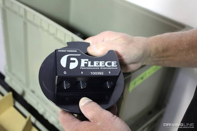
The most recognizable piece of the PowerFlo in-tank lift pump is the cap. Once installed, it sits above the tank. The cap incorporates a ½-inch feed fitting and a 3/8-inch return fitting to accommodate the factory quick-disconnect fuel lines. It also features a fuel vent (left-most port).
Support Rods
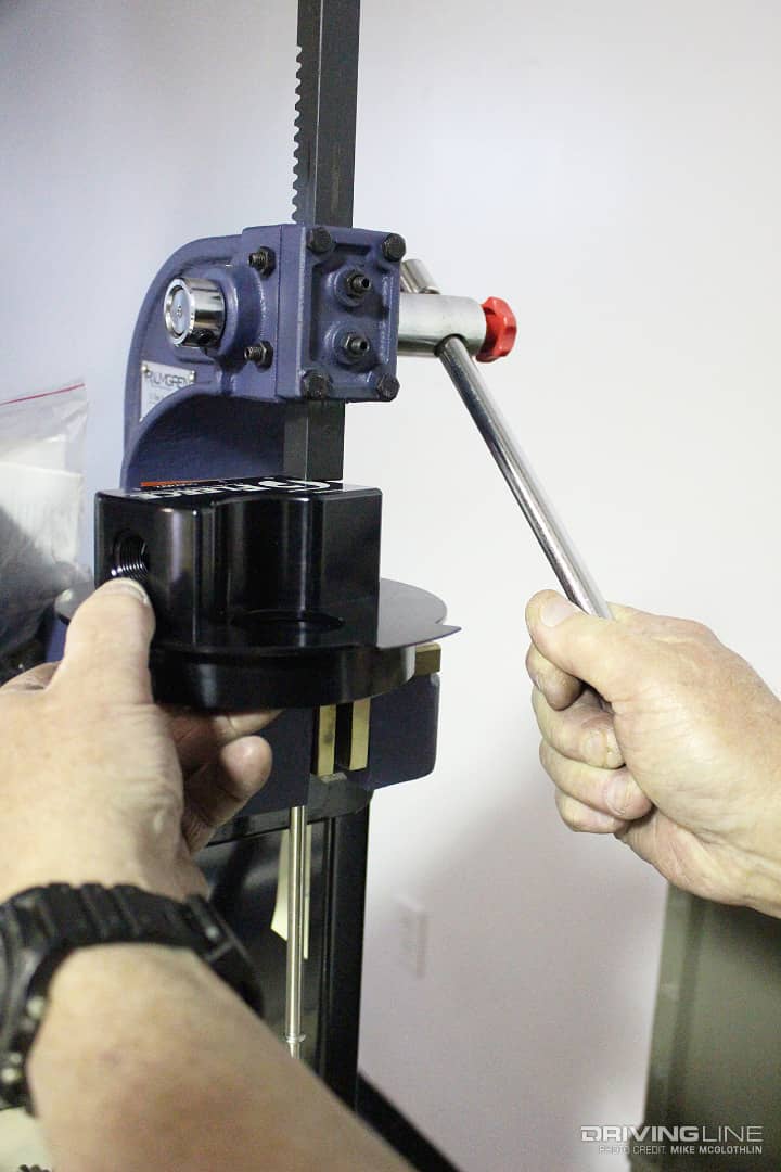
Assembly of a PowerFlo in-tank lift pump begins with its two support rods being pressed into the cap. The support rods will be linked to the pump bucket assembly (the bottom portion of the lift pump) later on. After this, a rubber grommet is installed in the head, followed by the plastic electrical connector that resides in the grommet.
Comes With Pre-Installed Fittings
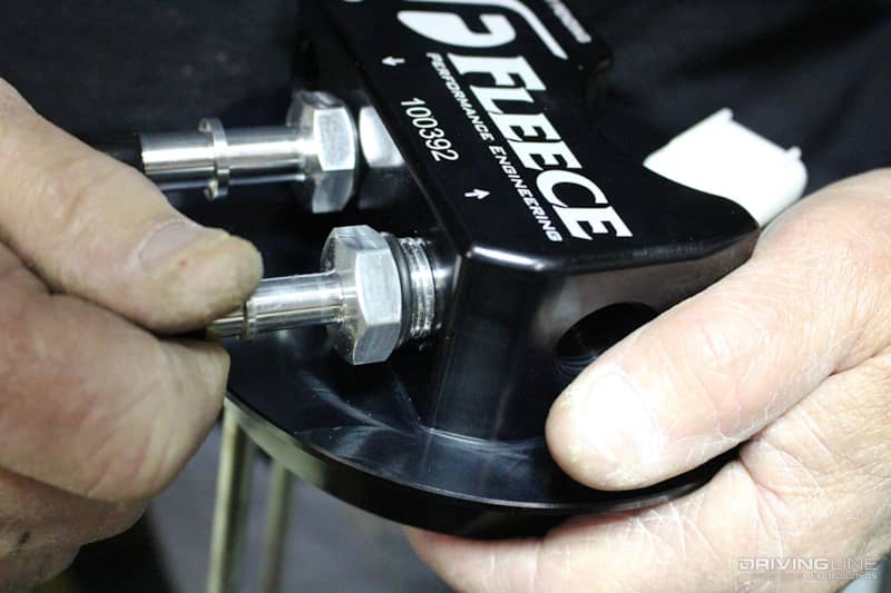
From there, the O-ringed ½-inch feed and 3/8-inch return fittings are installed and torqued to spec. After that, the same is done for the vent tube fitting. All fittings are then capped off to keep unwanted debris out during shipping.
Regulated Fuel Return
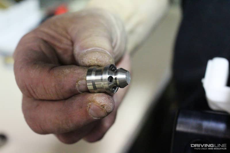
Next, the poppet valve is installed in the pressure regulator bore in the the cap (nearest to the return fitting). This is followed by the properly-tensioned pressure regulator spring and poppet valve plug. By regulating the fuel returning to the tank, no overpressure scenarios can occur.
Two Gerotors, Two Feed Fittings
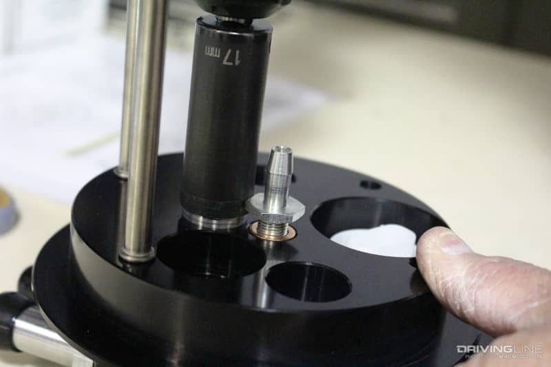
Because there are two gerotor pumps side by side within the pump bucket assembly, each unit has its own fuel feed line running to the cap (toward the engine). With the cap turned upside down, both feed fittings are threaded in and torqued to spec.
Drain Tube Secured
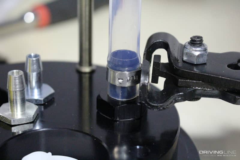
Once the vent fitting and rollover valve have been installed in the cap assembly, the drain tube barb fitting comes next. Then the drain hose is pressed onto the barbed fitting, with a crimped retainer clamp also being installed over the hose to ensure it can never work itself loose.
Adding the Pump Bucket Assembly
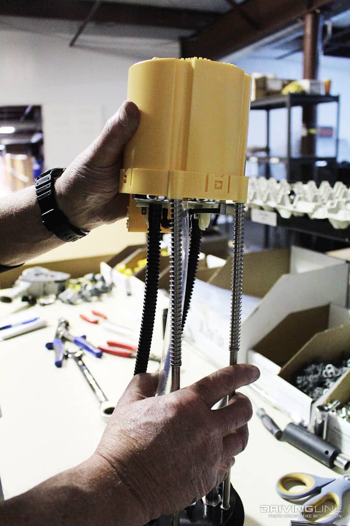
After springs have been installed on the ends of the support rods (previously pressed into the cap), the support rods are pressed into the pump bucket assembly. At this point, and since the pump-to-cap feed lines are already attached to the gerotor pumps, the feed lines from the pumps are connected to the previously-installed feed fittings.
Wired Up
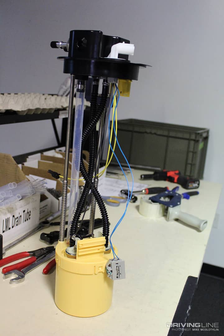
The pump-to-cap wiring harness comes next in the assembly process. The harness entails a power and ground wire for each gerotor pump, a fuel card (tested in-house in conjunction with the float arm for optimum accuracy) that attaches to the pump bucket by locking in place and a pigtail that plugs into the connector previously installed in the cap’s rubber grommet.
Dual Gerotor Pumps
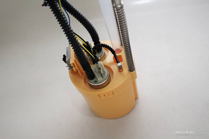
Thanks to the use of twin gerotor pumps, the PowerFlo in-tank lift pump flows 168 gph at 15 psi. This makes it comparable to the 165 gph external lift pumps common in the diesel aftermarket, but its in-tank design means no noisy pump gets mounted along your frame rail and winter gel-ups aren’t a worry. In addition, the fact that the gerotor pumps are of OE quality means that they’re extremely durable, having been tested to last at least 300,000 miles (or 12,000 hours).
Active Fill Technology
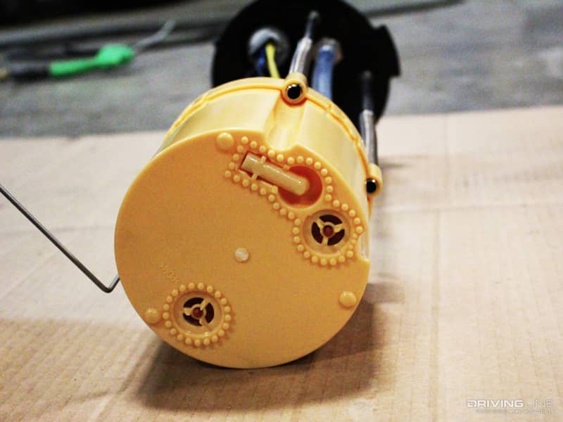
Another aspect that sets Fleece’s PowerFlo lift pump apart from the rest of the aftermarket systems is its active fill technology. By using a venturi effect on the bottom of the fill bucket assembly (and the fill bucket itself sitting in a well), it’s able to scavenge fuel off the bottom of the tank at all times. This means no low-fuel (i.e. ¼-tank) issues. As to how the PowerFlo lift pump compares to other systems, we think Fleece put it best: “If you have a tank sump or an aftermarket system with a draw straw, you’re going to suck air at some point—there’s no way around it. Our system avoids this by having a reservoir that is flooded at all times (active fill bucket), even under hard acceleration or deceleration with a nearly empty tank. A sump or draw straw cannot do that.”
New Float Arm
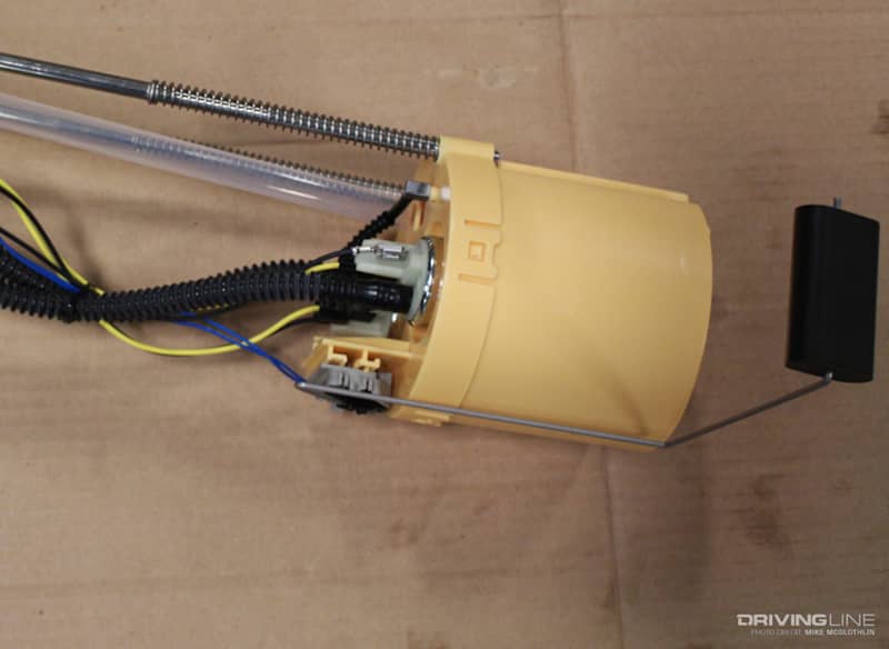
Although it’s something the end-user installs, attaching the fuel float arm is the last item of business as far as the lift pump’s in-tank installation is concerned. At our request, the guys at Fleece illustrated exactly how the float arm attaches to the fuel card (shown above).
Installation Kit
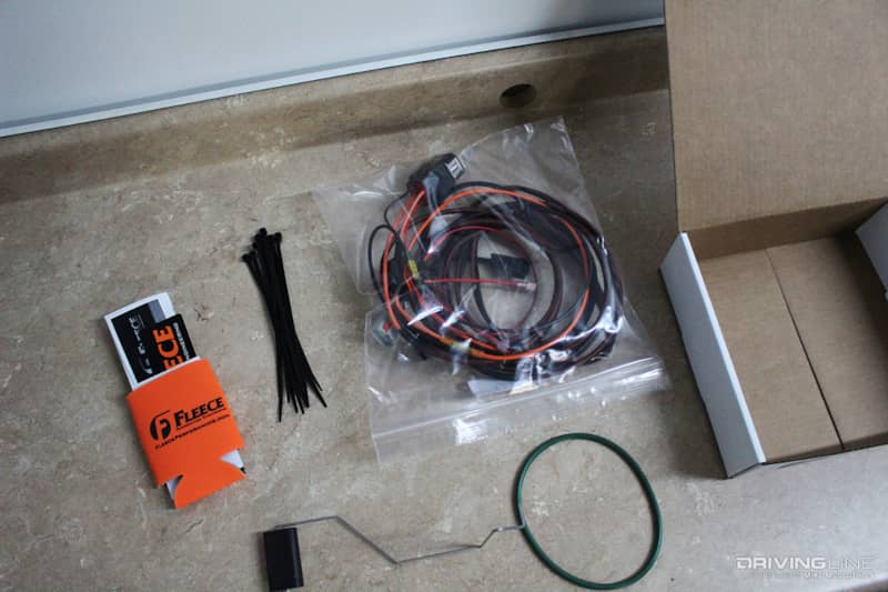
The only thing left to do now was remove the float arm and pack the rest of the installation accessories up for shipping. In order to ensure consistent voltage always makes it to the PowerFlo lift pump, Fleece supplies a dedicated fuel pump relay with its wiring harness, along with zip ties and a fresh flange seal.
Another CP4.2 Savior Is Ready to Ship
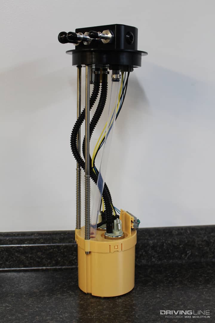
Here, in finished form, the LML PowerFlo in-tank lift pump is ready to keep an LML’s CP4.2 alive for the long-haul, feed dual injection pumps if it needs to or support as much as 800rwhp. It’s capable of doing all of the above. Also available for ’05-’18 5.9L and 6.7L Cummins applications, thus far the LML Duramax-intended PowerFlo lift pump is already a hot-ticket item. Further Duramax applications will soon be supported, too. Even further into the future, Fleece has hinted that Power Stroke engines with HEUI injection (systems that require 65 psi) might be supported, thanks to the company’s gerotor pumps being rated up to 100 psi.


